在Youtube上看见大牛用超声波传感器结合Processing实现雷达的效果,在度娘找不到此类文章,于是便想将原文翻译出来。
开始
一个超声波雷达的实现非常简单,使用超声波传感器侦测物件距离,使用舵机将挂在其上的传感器旋转,再用Arduino控制他们。

Youtube链接:Arduino_Radar_Project
需要的物件
1.Arduino版
2.超声波传感器 – HC-SR04
3.舵机 – SG90
4.面包板
5.杜邦线
设备制作
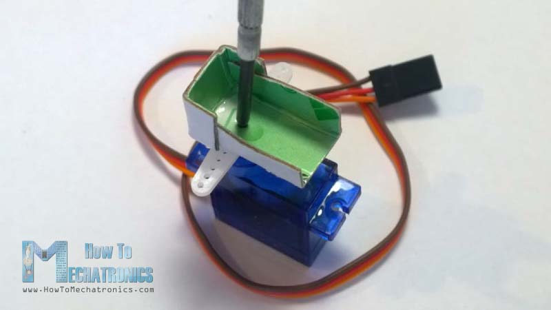
- 首先,制作一个纸板固定超声波传感器,并且使其固定在舵机上。我将纸板建成长方形,在其『长』的黄金分割处的左右各剪一刀,每刀应为『宽』的1/5。然后将两边折起,并用胶水黏住。再将其对准舵机叶片,钻上一洞,使其稳定固定在舵机上。
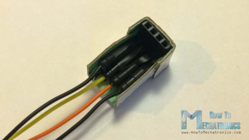
- 再者,将4条杜邦线母头粘连在一起,母头对上,以至能与超声波传感器公头连接。
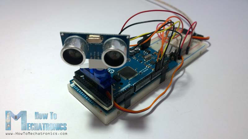
- 最后,我用橡皮筋将舵机固定在板(桌面)上,以防在转动时舵机自转。
电路连接
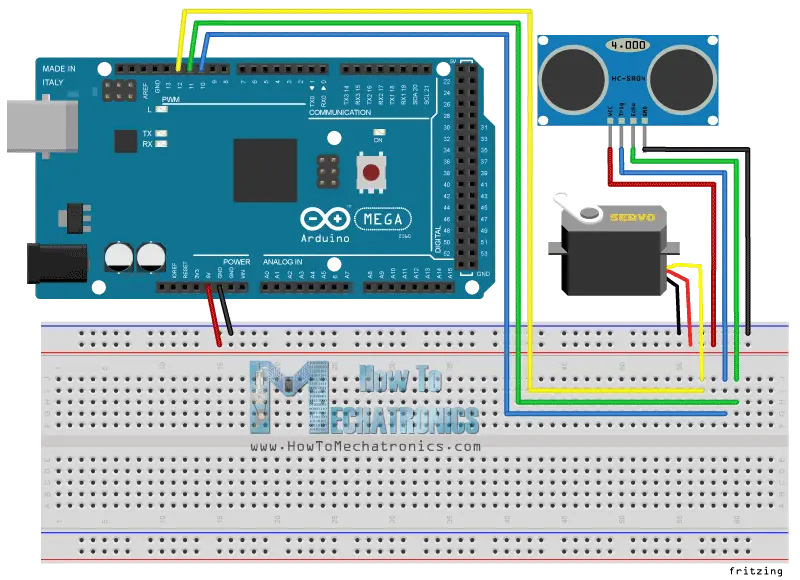
我将HC-SR04连接到Arduino的10号和11号针脚,而舵机则连接到12号针脚。
源代码
现在,我们需要写一段代码并上传到Arduino,并使Processing IDE与Arduino产生交互。想弄清楚如何连接,请看Arduino and Processing Tutorial。
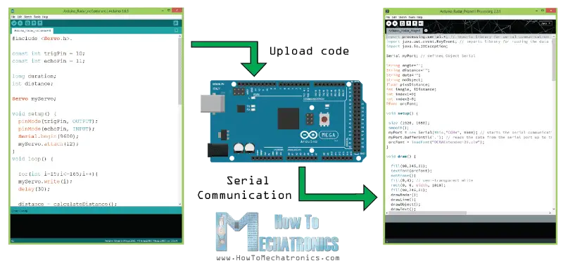
以下为Arduino Code,每条代码都带有注释
// Includes the Servo library
#include <Servo.h>.

// Defines Tirg and Echo pins of the Ultrasonic Sensor
const int trigPin = 10;
const int echoPin = 11;
// Variables for the duration and the distance
long duration;
int distance;

Servo myServo; // Creates a servo object for controlling the servo motor

void setup() {
  pinMode(trigPin, OUTPUT); // Sets the trigPin as an Output
  pinMode(echoPin, INPUT); // Sets the echoPin as an Input
  Serial.begin(9600);
  myServo.attach(12); // Defines on which pin is the servo motor attached
}
void loop() {
  // rotates the servo motor from 15 to 165 degrees
  for(int i=15;i<=165;i++){
  myServo.write(i);
  delay(30);
  distance = calculateDistance();// Calls a function for calculating the distance measured by the Ultrasonic sensor for each degree

  Serial.print(i); // Sends the current degree into the Serial Port
  Serial.print(","); // Sends addition character right next to the previous value needed later in the Processing IDE for indexing
  Serial.print(distance); // Sends the distance value into the Serial Port
  Serial.print("."); // Sends addition character right next to the previous value needed later in the Processing IDE for indexing
  }
  // Repeats the previous lines from 165 to 15 degrees
  for(int i=165;i>15;i--){
  myServo.write(i);
  delay(30);
  distance = calculateDistance();
  Serial.print(i);
  Serial.print(",");
  Serial.print(distance);
  Serial.print(".");
  }
}
// Function for calculating the distance measured by the Ultrasonic sensor
int calculateDistance(){

  digitalWrite(trigPin, LOW);
  delayMicroseconds(2);
  // Sets the trigPin on HIGH state for 10 micro seconds
  digitalWrite(trigPin, HIGH);
  delayMicroseconds(10);
  digitalWrite(trigPin, LOW);
  duration = pulseIn(echoPin, HIGH); // Reads the echoPin, returns the sound wave travel time in microseconds
  distance= duration*0.034/2;
  return distance;
}
现在,我们会接收到传感器的舵机移动角度与距离,使用 SerialEvent() 函数读取串行端口数据,并将这些数据传入Processing IDE中,我们分别用iAngle 和 iDistance 表示角度与距离。这些数据将用来绘制雷达(包含:线条、侦测反馈和一些文字)。
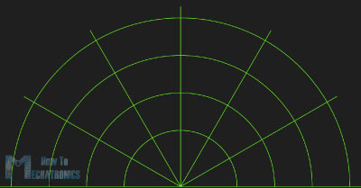
为了绘制雷达,我们使用 drawRadar() 函数,它将包含 arc() 和 line()。
void drawRadar() {
  pushMatrix();
  translate(960,1000); // moves the starting coordinats to new location
  noFill();
  strokeWeight(2);
  stroke(98,245,31);
  // draws the arc lines
  arc(0,0,1800,1800,PI,TWO_PI);
  arc(0,0,1400,1400,PI,TWO_PI);
  arc(0,0,1000,1000,PI,TWO_PI);
  arc(0,0,600,600,PI,TWO_PI);
  // draws the angle lines
  line(-960,0,960,0);
  line(0,0,-960*cos(radians(30)),-960*sin(radians(30)));
  line(0,0,-960*cos(radians(60)),-960*sin(radians(60)));
  line(0,0,-960*cos(radians(90)),-960*sin(radians(90)));
  line(0,0,-960*cos(radians(120)),-960*sin(radians(120)));
  line(0,0,-960*cos(radians(150)),-960*sin(radians(150)));
  line(-960*cos(radians(30)),0,960,0);
  popMatrix();
}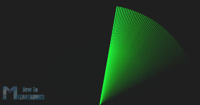
使用 drawLine() 来绘制雷达上移动的绿色线条。其中它的旋转中心使用 translate() 函数跟踪,再用 line() 函数配合 iAngle 值重绘每一个角度。
void drawLine() {
  pushMatrix();
  strokeWeight(9);
  stroke(30,250,60);
  translate(960,1000); // moves the starting coordinats to new location
  line(0,0,950*cos(radians(iAngle)),-950*sin(radians(iAngle))); // draws the line according to the angle
  popMatrix();
}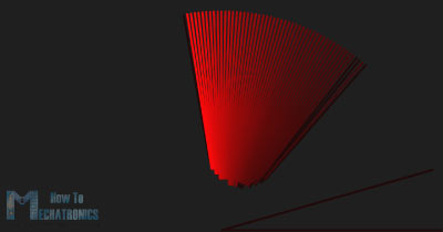
使用 drawObject() 来绘制侦测物体后的红色反馈。它将超声波传感器获得的距离转换为像素,再结合传感器角度在雷达上绘制出来。
void drawObject() {
  pushMatrix();
  translate(960,1000); // moves the starting coordinats to new location
  strokeWeight(9);
  stroke(255,10,10); // red color
  pixsDistance = iDistance*22.5; // covers the distance from the sensor from cm to pixels
  // limiting the range to 40 cms
  if(iDistance<40){
    // draws the object according to the angle and the distance
  line(pixsDistance*cos(radians(iAngle)),-pixsDistance*sin(radians(iAngle)),950*cos(radians(iAngle)),-950*sin(radians(iAngle)));
  }
  popMatrix();
}
使用 drawText() 函数,在特定的位置描绘文字。
所有这些重复描绘屏幕的函数都定义在函数 draw() 内,同时,我们使用带两个参数的 fill() 函数模拟运动中模糊和缓慢消退的线条。
void draw() {

  fill(98,245,31);
  textFont(orcFont);
  // simulating motion blur and slow fade of the moving line
  noStroke();
  fill(0,4);
  rect(0, 0, width, 1010);

  fill(98,245,31); // green color
  // calls the functions for drawing the radar
  drawRadar();
  drawLine();
  drawObject();
  drawText();
}
这里就是最后出现的雷达啦!
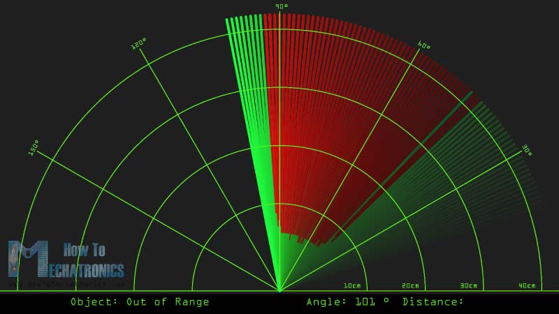
import processing.serial.*; // imports library for serial communication
import java.awt.event.KeyEvent; // imports library for reading the data from the serial port
import java.io.IOException;

Serial myPort; // defines Object Serial
// defubes variables
String angle="";
String distance="";
String data="";
String noObject;
float pixsDistance;
int iAngle, iDistance;
int index1=0;
int index2=0;
PFont orcFont;

void setup() {

 size (1920, 1080);
 smooth();
 myPort = new Serial(this,"COM4", 9600); // starts the serial communication
 myPort.bufferUntil('.'); // reads the data from the serial port up to the character '.'. So actually it reads this: angle,distance.
 orcFont = loadFont("OCRAExtended-30.vlw");
}

void draw() {

  fill(98,245,31);
  textFont(orcFont);
  // simulating motion blur and slow fade of the moving line
  noStroke();
  fill(0,4);
  rect(0, 0, width, 1010);

  fill(98,245,31); // green color
  // calls the functions for drawing the radar
  drawRadar();
  drawLine();
  drawObject();
  drawText();
}

void serialEvent (Serial myPort) { // starts reading data from the Serial Port
  // reads the data from the Serial Port up to the character '.' and puts it into the String variable "data".
  data = myPort.readStringUntil('.');
  data = data.substring(0,data.length()-1);

  index1 = data.indexOf(","); // find the character ',' and puts it into the variable "index1"
  angle= data.substring(0, index1); // read the data from position "0" to position of the variable index1 or thats the value of the angle the Arduino Board sent into the Serial Port
  distance= data.substring(index1+1, data.length()); // read the data from position "index1" to the end of the data pr thats the value of the distance

  // converts the String variables into Integer
  iAngle = int(angle);
  iDistance = int(distance);
}

void drawRadar() {
  pushMatrix();
  translate(960,1000); // moves the starting coordinats to new location
  noFill();
  strokeWeight(2);
  stroke(98,245,31);
  // draws the arc lines
  arc(0,0,1800,1800,PI,TWO_PI);
  arc(0,0,1400,1400,PI,TWO_PI);
  arc(0,0,1000,1000,PI,TWO_PI);
  arc(0,0,600,600,PI,TWO_PI);
  // draws the angle lines
  line(-960,0,960,0);
  line(0,0,-960*cos(radians(30)),-960*sin(radians(30)));
  line(0,0,-960*cos(radians(60)),-960*sin(radians(60)));
  line(0,0,-960*cos(radians(90)),-960*sin(radians(90)));
  line(0,0,-960*cos(radians(120)),-960*sin(radians(120)));
  line(0,0,-960*cos(radians(150)),-960*sin(radians(150)));
  line(-960*cos(radians(30)),0,960,0);
  popMatrix();
}

void drawObject() {
  pushMatrix();
  translate(960,1000); // moves the starting coordinats to new location
  strokeWeight(9);
  stroke(255,10,10); // red color
  pixsDistance = iDistance*22.5; // covers the distance from the sensor from cm to pixels
  // limiting the range to 40 cms
  if(iDistance<40){
    // draws the object according to the angle and the distance
  line(pixsDistance*cos(radians(iAngle)),-pixsDistance*sin(radians(iAngle)),950*cos(radians(iAngle)),-950*sin(radians(iAngle)));
  }
  popMatrix();
}

void drawLine() {
  pushMatrix();
  strokeWeight(9);
  stroke(30,250,60);
  translate(960,1000); // moves the starting coordinats to new location
  line(0,0,950*cos(radians(iAngle)),-950*sin(radians(iAngle))); // draws the line according to the angle
  popMatrix();
}

void drawText() { // draws the texts on the screen

  pushMatrix();
  if(iDistance>40) {
  noObject = "Out of Range";
  }
  else {
  noObject = "In Range";
  }
  fill(0,0,0);
  noStroke();
  rect(0, 1010, width, 1080);
  fill(98,245,31);
  textSize(25);
  text("10cm",1180,990);
  text("20cm",1380,990);
  text("30cm",1580,990);
  text("40cm",1780,990);
  textSize(40);
  text("Object: " + noObject, 240, 1050);
  text("Angle: " + iAngle +" °", 1050, 1050);
  text("Distance: ", 1380, 1050);
  if(iDistance<40) {
  text("        " + iDistance +" cm", 1400, 1050);
  }
  textSize(25);
  fill(98,245,60);
  translate(961+960*cos(radians(30)),982-960*sin(radians(30)));
  rotate(-radians(-60));
  text("30°",0,0);
  resetMatrix();
  translate(954+960*cos(radians(60)),984-960*sin(radians(60)));
  rotate(-radians(-30));
  text("60°",0,0);
  resetMatrix();
  translate(945+960*cos(radians(90)),990-960*sin(radians(90)));
  rotate(radians(0));
  text("90°",0,0);
  resetMatrix();
  translate(935+960*cos(radians(120)),1003-960*sin(radians(120)));
  rotate(radians(-30));
  text("120°",0,0);
  resetMatrix();
  translate(940+960*cos(radians(150)),1018-960*sin(radians(150)));
  rotate(radians(-60));
  text("150°",0,0);
  popMatrix();
}
参考链接
http://howtomechatronics.com/projects/arduino-radar-project/
发表回复